A&A CORVETTE C7 SUPERCHARGER SYSTEM

INSTALLATION INSTRUCTIONS FOR THE C7 CORVETTE
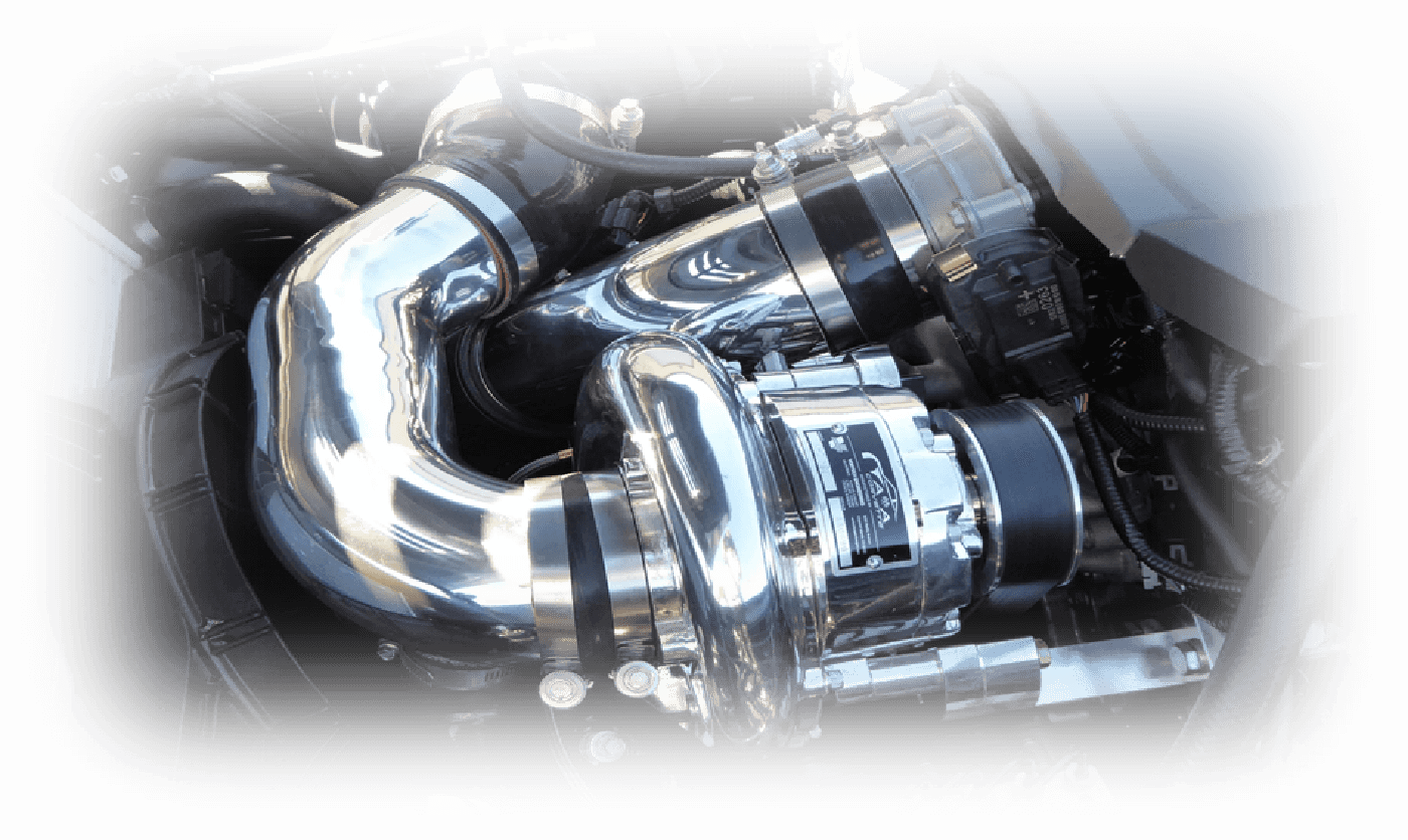
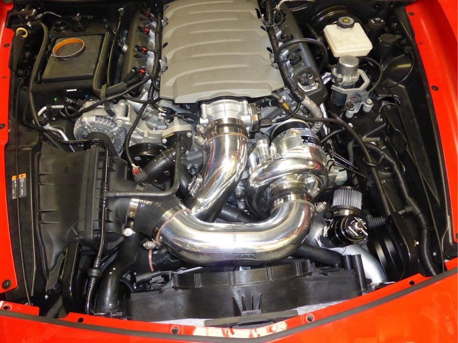
A&A SUPERCHARGER FOR C7 CORVETTE

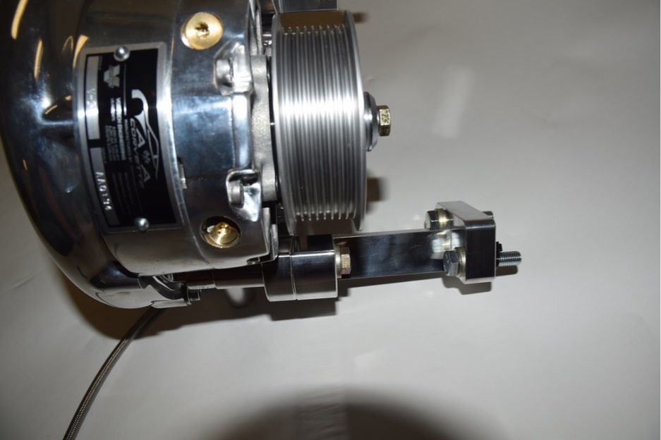
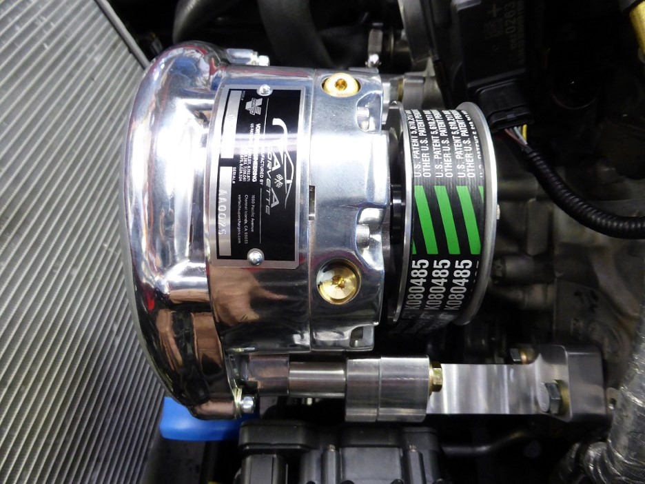
A&A CORVETTE PERFORMANCE C7 SUPERCHARGER
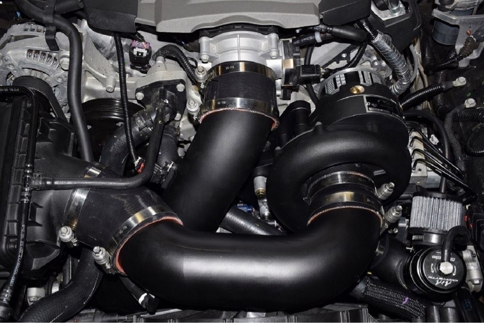
A&A CORVETTE PERFORMANCE C7 SUPERCHARGER INSTALLATION INSTRUCTIONS
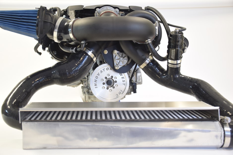
GETTING STARTED


The supercharger install is very straightforward and can be performed at home with basic mechanical skills and tools. Once finished, everything will fit under the stock hood and all covers, including the radiator to hood heat extractor will fit back on the vehicle. The car will need to be raised on jackstands or a lift for proper access to the underside of the vehicle.
PROP UP OR REMOVE THE HOOD

  • Disconnect the struts from the hood and prop the hood up with a piece of wood. A 1 X 2 or a broom stick works best. 41” seems to be about the right length. Wrap and fold a shop rag around the end to prevent scratching the hood.


  • Access to the front of the engine will be easier with the hood removed. It is not a necessity but it will make the job easier.


  • Should you opt to remove the hood, mark the outer circumference of the hood bolts with a marker or scribe to maintain proper alignment when reinstalling the hood. While someone holds the hood, remove the two 13MM bolts holding the hood hinge assembly to the hood. Remove the hood and put it in a safe place.

REMOVE THE STOCK AIR FILTER AND DUCTING

  • Remove the stock air inlet duct by removing the clamps at either end and releasing the quick-connect emissions fittings.


  • Remove the factory air filter cover and filter using a # 25 Torx bit. Remove the MAF sensor from the cover. Also remove the screen inside the air filter cover. It does not appear to be attached very securely and could possibly become detached with the increased airflow. Set the MAF sensor aside as it will be installed in its new location later in the installation process.


  • The neck of the filter cover will need to be cut off just behind the MAF sensor mounting boss. You want this area to be as short as possible while leaving it long enough to attach a silicone coupler and clamp. We suggest you wrap a piece of 3/4 masking tape around the neck as close to the base as possible. This will guide you in cutting the plastic neck squarely. There are a couple of small ribs that will require sanding off to allow the hose to seat properly as well. Do not overtighten!

MOVE THE RADIATOR HOSE

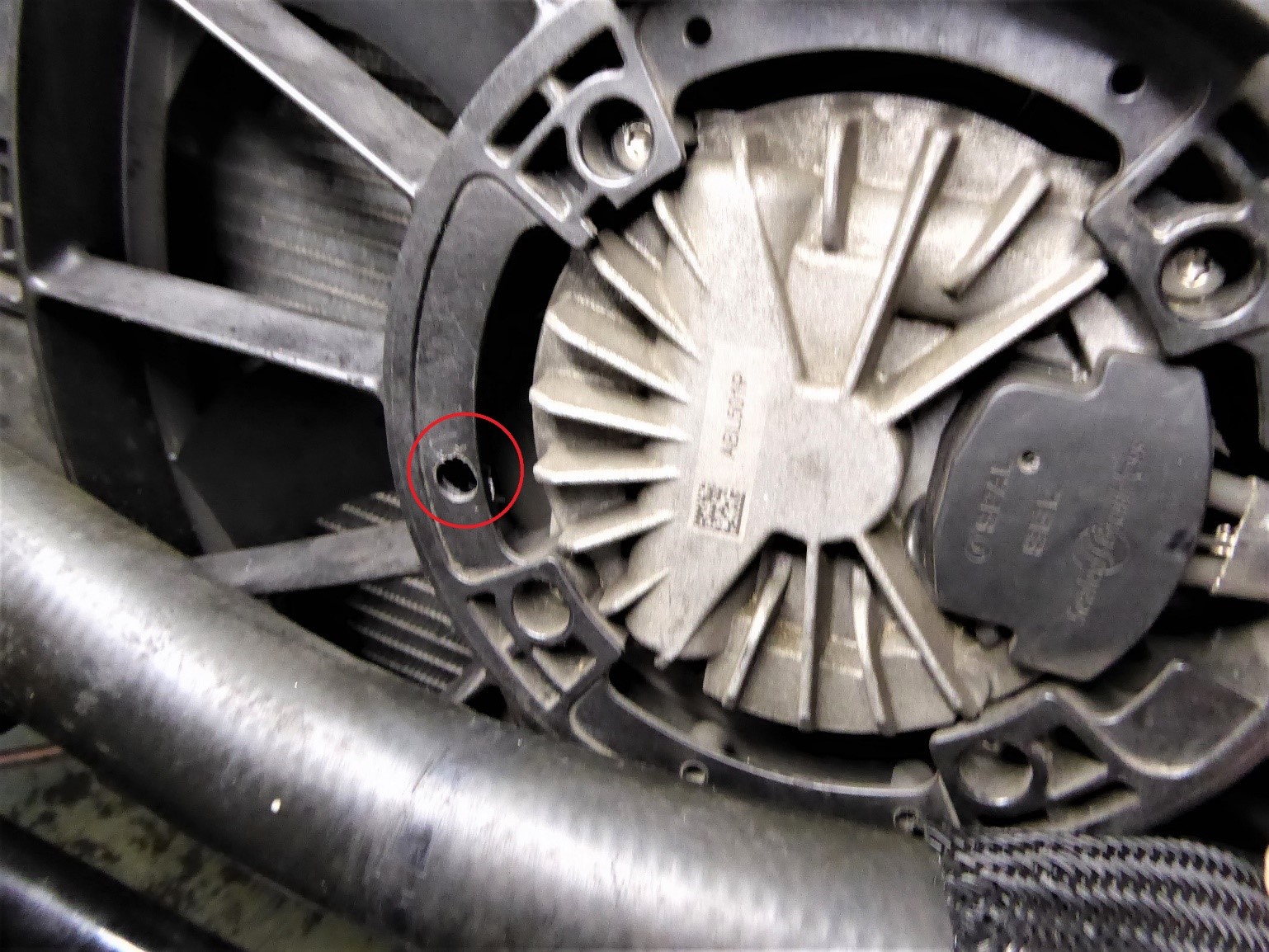
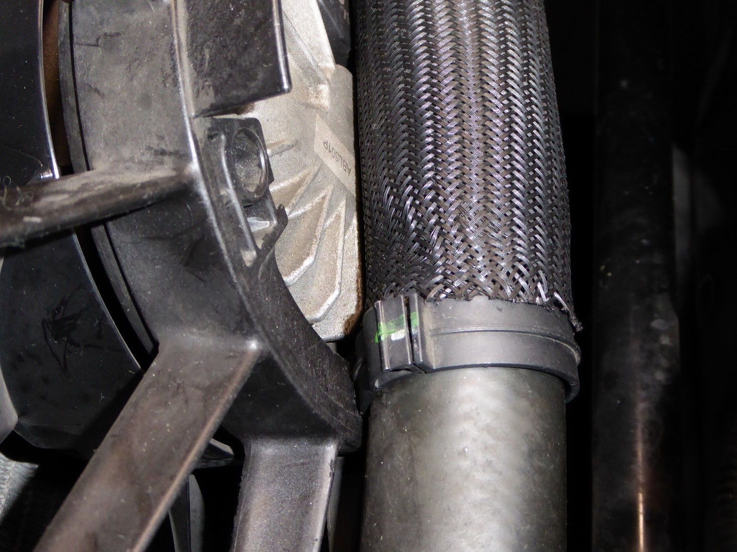
  • The factory radiator hose is moved slightly in order to clear the supercharger tubing. Pull the hose away from the fan housing. This will release the two “push pin” style clips holding it in place. Remove one of the clips from the hose. Drill a 21/64 hole in the housing at about the 8:30 position as shown. (you can also use a standard 5/16 bit and just ream the hole out a little larger) Slide the protective sleeve on the hose so it is centered on the fan motor. Move the remaining clip up the hose to align with the new hole you drilled and push it in. Pay attention to clearance between the MAF sensor and the hose later on in the installation process. If it’s too close for comfort, simply zip tie it to the other coolant hose to pull it away slightly.

(HOLE DRILLED IN FAN HOUSING)

(HOSE SECURED WITH FACTORY PUSH PIN RETAINER)
REMOVE THE FRONT SWAY BAR

  • Raise the front end of the vehicle to gain access to the underside. Jackstands will be sufficient. Make sure the rear wheels are chocked, parking brake is engaged and there is no possibility of the car moving.


  • Remove both front wheels. 


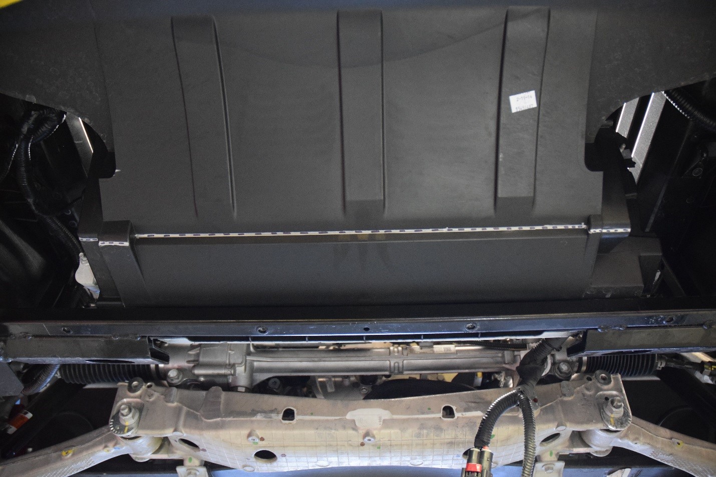
  • Remove the large flat panel below the front fascia. A new one is included with your kit.


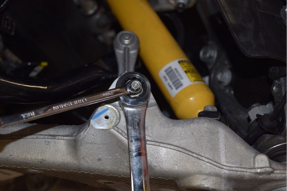
  • Remove the 18MM nut attaching the end link to the lower control arm using an 8MM wrench to stop the stud from spinning.

(SWAY BAR END LINK REMOVAL)
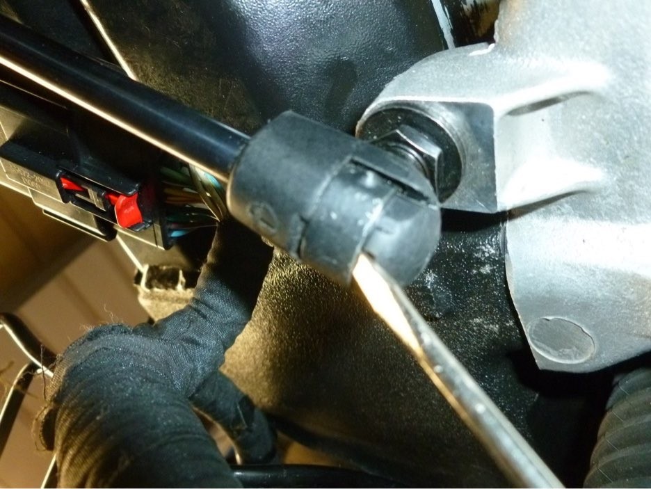
  • Locate the bottom of the hood strut and pop the retainer clip out as shown. Alternatively, as the strut is already disconnected at the top, you can just remove the sway bar bracket with the strut attached.

(HOOD STRUT ATTACHED TO SWAY BAR MOUNTING BRACKET)

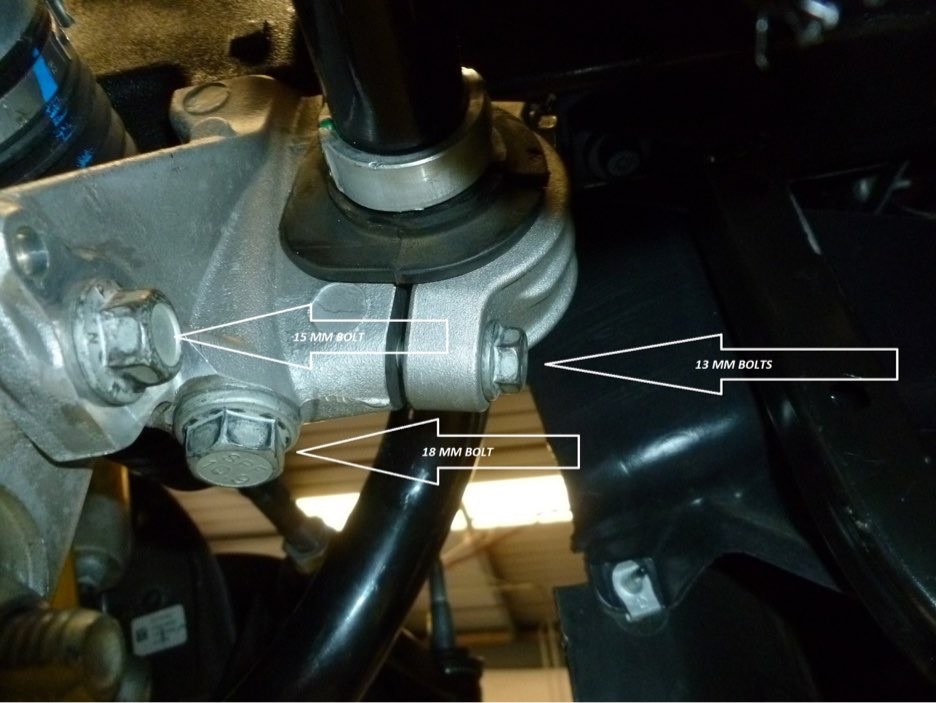
  • Remove the two 13MM bolts holding the sway bar retaining cap to the mount assembly. The sway bar can now be removed from the car.


  • The sway bar mount assembly is removed by taking out the 15MM bolt attaching it to the engine cradle and the long 18 MM bolt attaching it to the frame.


  • Disconnect the small hose at the lower left of the radiator by popping the clip out of the quick connect fitting. This will make it much easier to get the sway bar out.

(SWAY BAR MOUNTING BRACKET)

REMOVE THE ELECTRIC STEERING RACK

  • The steering rack will be removed to install the A&A custom damper. Once the sway bar mounts are out of the way, the steering rack is extremely easy to remove. It really is a 10-15 minute job. As a matter of fact, once everything is disconnected, you need to be careful that it doesn’t actually fall out of the car.


  • Before attempting to remove the rack, make sure the wheels are straight. Do not allow the steering wheel to turn while the rack is disconnected. You might even tie the wheel straight with a bungie cord or rope to make sure. Small movements are fine. Just don’t let it spin a full turn.


  • Disconnect the wire harness plug from the power steering motor. Disconnect the harness plug from the fan assembly. Remove the two 10MM bolts holding the fan in place and lift it out. This is not necessary but we’ve found it easier to work with the added room afforded by taking the fan out of the car.


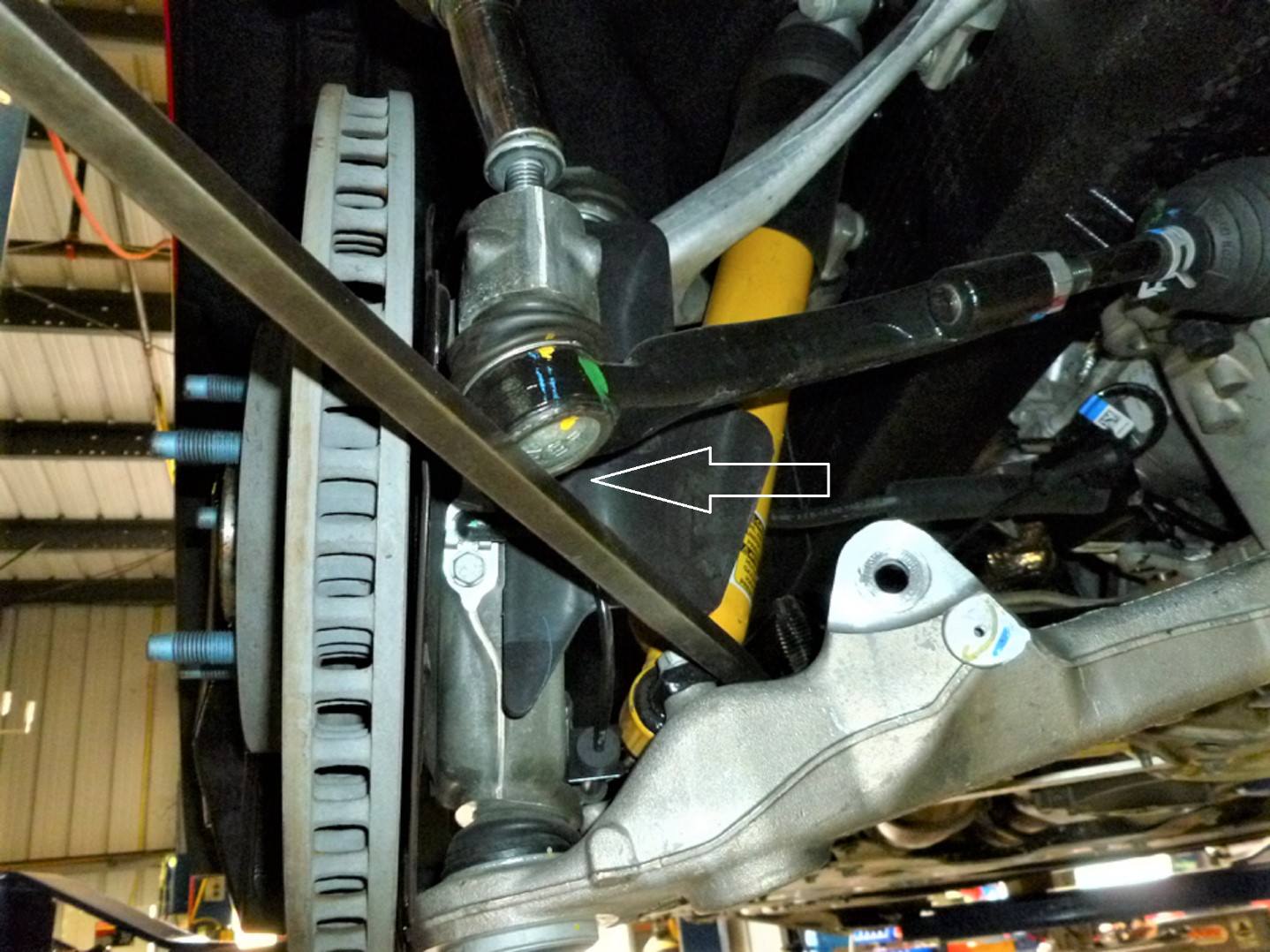
  • Remove the 18MM nuts at the end of the steering rack where the studs go through the spindles. If the stud spins, you may have to pry upwards on the tie rod end, pushing the tapered stud into the spindle to stop it. If the nut comes off but the stud is stuck in the spindle, leave the nut on loosely, to protect the threads, and tap it with a brass hammer or a piece of wood and a regular hammer.

(PRY UPWARDS HERE ONLY IF THE STUD SPINS IN THE SPINDLE)

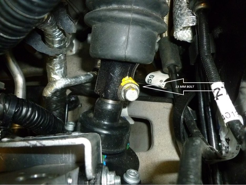
(REMOVE THIS BOLT- SLIDE SHAFT TOWARDS FIREWALL TO DISCONNECT)

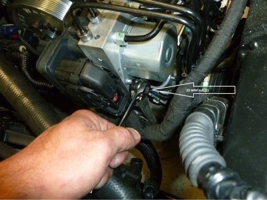
  • Remove the factory ABS module mounting bracket by loosening the two 10 MM nuts on the outboard side of the module. The module will lift out of the bracket once the nuts are loose. Just lift the module slightly so it is free of the bracket. Now go below and remove the two 13MM bolts attaching the bracket to the engine cradle. The bracket can now be removed from the car. 

(ABS MODULE ATTACHMENT NUTS AND BUSHINGS)

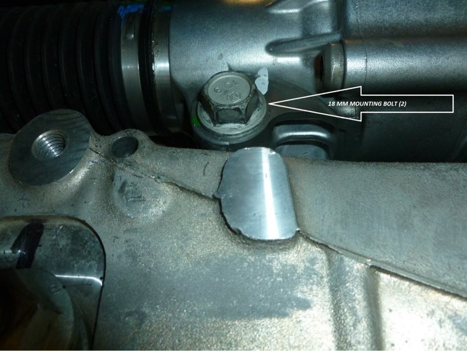
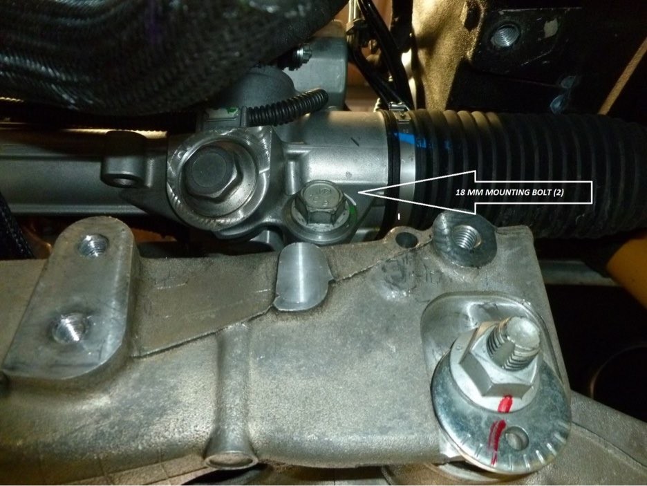
  • Remove the 18MM steering rack mounting bolts. The rack will now lift out of the car from the front. A slight movement to the left is all that is needed to clear one of the water hoses. Be careful that, once the mounting bolts are removed, the rack doesn’t fall out.

LEFT SIDE STEERING RACK MOUNTING BOLT

(RIGHT SIDE STEERING RACK MOUNTING BOLT)

REMOVE THE STOCK BALANCER

  • Remove the harmonic balancer bolt with a 24MM socket. A STRONG impact gun is best for this.


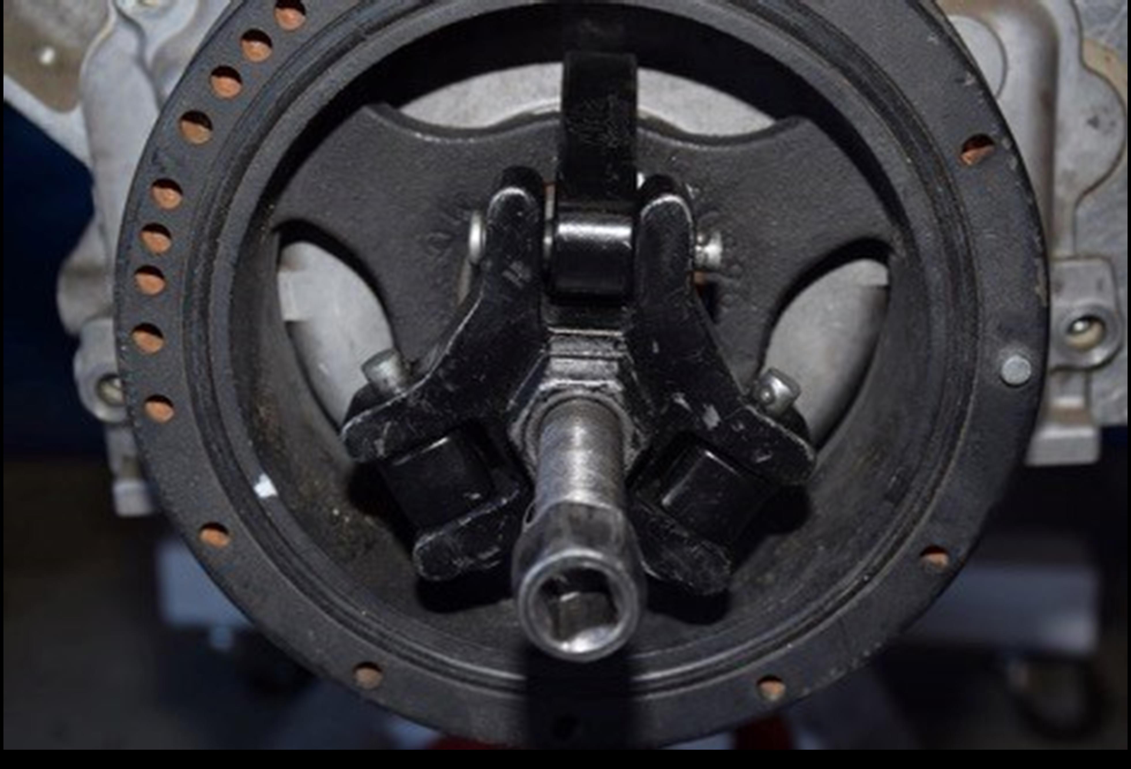
  • Install a standard 3 jaw balancer puller and remove the balancer. (These may be rented at most auto parts stores)

(BALANCER PULLER INSTALLED)

INSTALL THE NEW BALANCER

  • Install the new SFI approved balancer using the supplied 16MM X 2.0X 160MM bolt as an installer tool. The standard balancer bolt is too short to start pulling the balancer onto the crankshaft. We’ve included a longer (160MM) bolt to use as an installer tool. (this will be the longer of the 2 supplied bolts) Put the thin flat washer on the bolt first, then the thick washer with the little step facing away from the bolt head. The thin washer is only used to prevent galling of the thick washer. Use the bolt to draw the balancer onto the crankshaft approximately 1 inch. Do not allow the installer bolt to bottom out in the hole. It will flatten the threads and, in turn, damage the threads in the crankshaft. Once the balancer is on that far, remove the bolt and replace it with the shorter bolt and the thick washer only. The little step should be towards the head of the bolt. Make sure you have enough threads in the crankshaft to safely pull the balancer on before proceeding. Put a little red Loctite on the threads and use that bolt to draw the balancer the remainder of the way on. Torque the balancer bolt to 130 pounds.


  • The crankshaft and balancer are keyed so no “pinning” of the crankshaft is needed as in previous generations of Corvette.


  • Reinstall the steering rack and sway bar in the reverse order they were removed.

RELOCATE THE ABS CONTROL MODULE

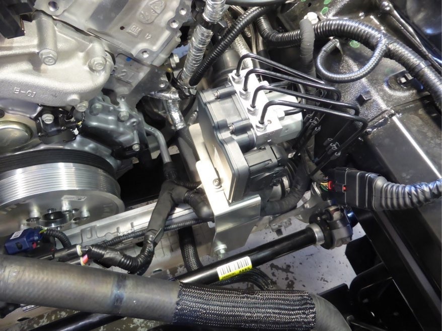
  • Slip the new bracket under the module and mount the module to the new bracket using the existing rubber grommets. Having the ABS box mounted in the bracket will allow you to see just how far and in what direction the module must be moved.


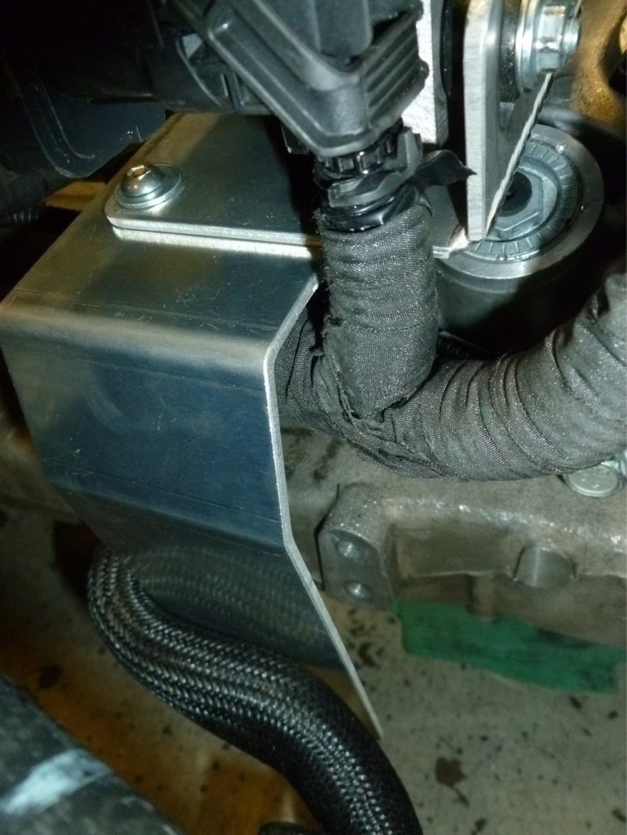
  • Very slightly loosen the lines, allowing them to rotate in their fittings as the box is moved. You’ll have to coax them a bit as the ABS module is moved. Turning them and slightly bending them individually works best. There are two lines that run along the frame rail as well. Bend these so as to allow the module to move closer to the frame rail. The ABS wire harness tucks behind the bracket as shown.

(WIRE HARNESS ROUTED BEHIND NEW ABS MODULE MOUNTING BRACKET)

  • Slowly move the ABS module and bracket, as an assembly, until the new bracket lines up with the original mounting holes in the engine cradle.


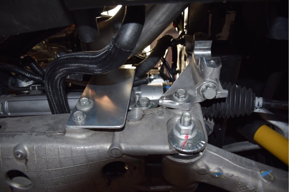
  • Install the two 13 MM bolts in the engine cradle, securing the new ABS module bracket. Retighten the brake lines. The bolt holes are slightly slotted so the bracket can be adjusted to clear the supercharger bracket once it is installed. (you may need to adjust it later) Once the lines are manipulated properly the ABS module WILL clear the supercharger housing. About 1/4” of clearance is fine.

(TNEW ABS BRACKET ATTACHED TO SUBFRAME)

 
(ABS MODULE AFTER RELOCATION)

INSTALL THE SUPERCHARGER AND BRACKET ASSEMBLY

 
(VENT TUBE- Z06 SHOWN)

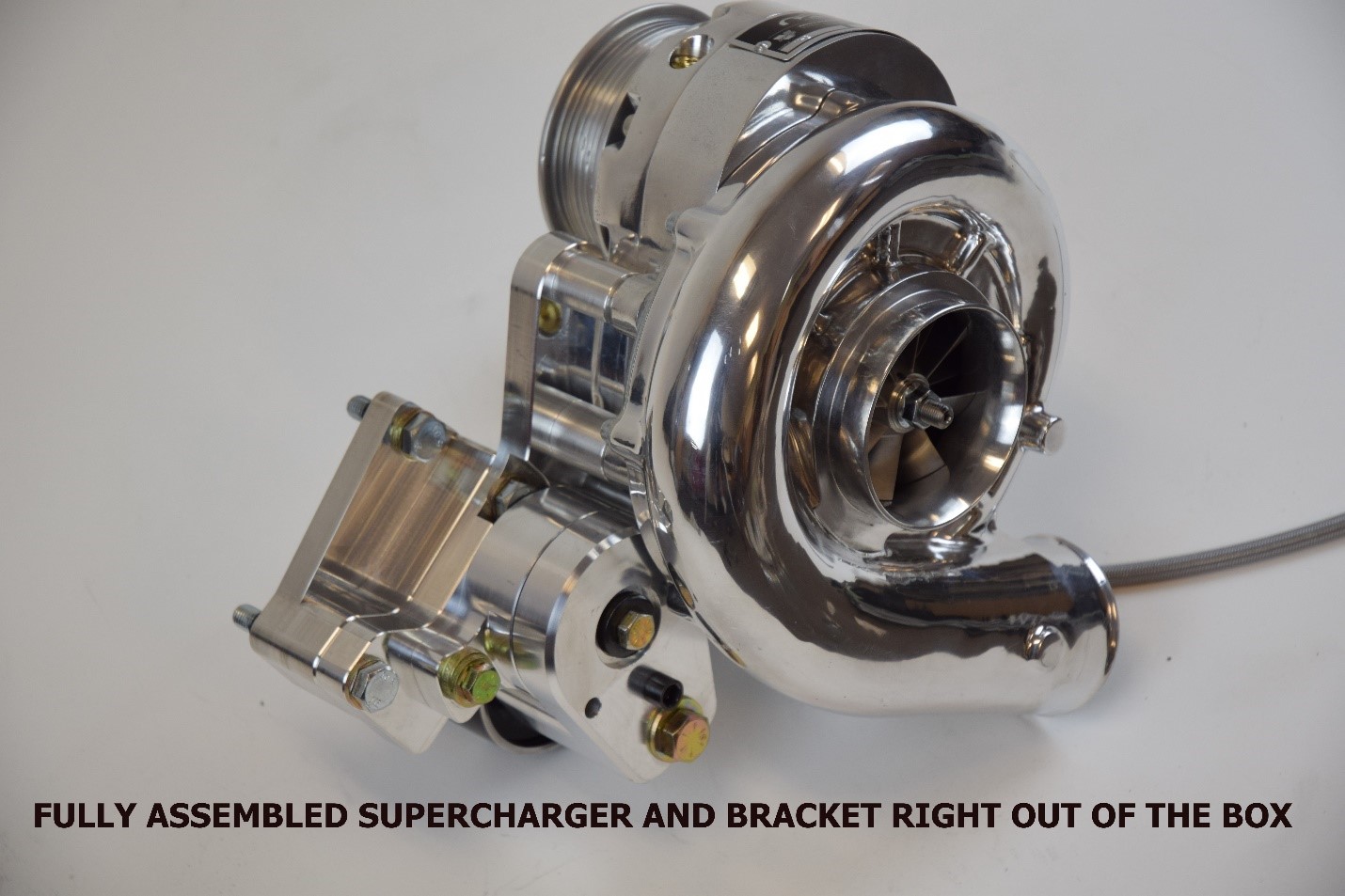
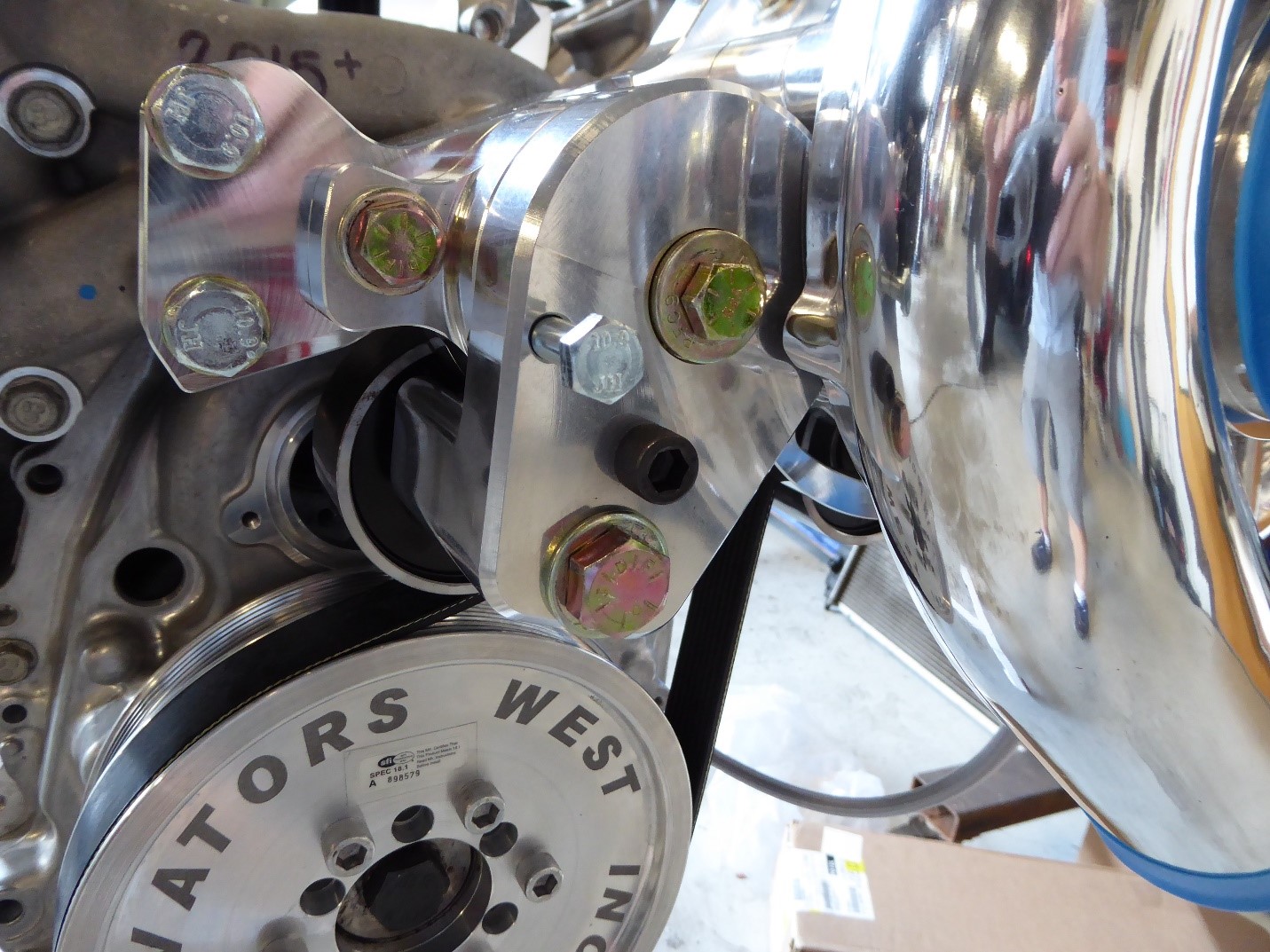
  • On 2014 vehicles the whole bracket assembly can be installed as is. The two 10MM bolts go directly into the water pump while the other two go into the cylinder head. You may have to loosen the cylinder head bracket to get a little wiggle room“ in order for the head bolts to line up. It should be pretty self explanatory once you actually do this.


  • On 2015 and up cars there is one small difference. You will see one bolt in the water pump mounting block is covered by the main bracket. You will have to separate the main bracket from the water pump bracket in order to get to this bolt. Once separated, bolt the water pump block to the water pump using the hidden bolt and one of the other bolts just to keep it aligned. Now bolt the main bracket back to the water pump block and the cylinder head bracket to the head in the same manner as the 2014.

(TWO BOLTS IN THIS BRACKET GO DIRECTLY TO THE CYLINDER HEAD)

INSTALLING THE BELT

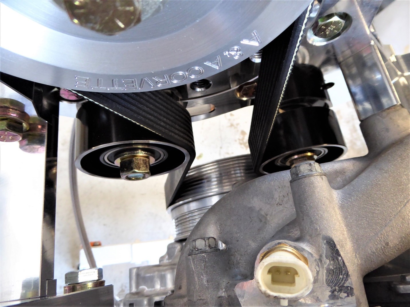
  • Move the smooth idler all the way towards the frame and snug it down slightly. (There is a long slot in the supercharger bracket to allow this movement)


  • Lock the tensioner in the open position by rotating the tensioner clockwise (from the front) with a ¾” socket. Once it is rotated almost to the end of its travel, insert the lock pin (5/16” bolt) into the open hole. Line this hole up with the one in the back portion of the tensioner and push the pin all the way in. The tensioner is now locked in the open position for easy belt installation.


  • Route the belt around the balancer, in between the spring tensioner and idler pulleys and around the supercharger pulley. Slide the idler pulley until it has slight pressure on the belt and tighten the bolt. Rotate the tensioner slightly, pull the lock pin out and release. This should be about right. Tensioner preload can be adjusted by moving the idler pulley in either direction. (Lock the tensioner in the open position before attempting to move the idler.)

(ADJUSTABLE SLIDING IDLER ON THE LEFT AND SPRING TENSIONER ON THE RIGHT)

(SPRING TENSIONER LOCKED IN THE SLACK POSITION)

  • NOTE: The tensioner also has 2 internal spring pressure settings that require disassembly of the tensioner. This is NOT something that needs to be done under normal circumstances. Only when building a max effort engine – supercharger combination would it be advantageous to increase the internal spring pressure. Contact A&A before attempting this. The spring inside is EXTREMELY strong and requires the proper procedure to change the setting without injuring yourself and damaging the tensioner.

(SIDE VIEW OF SUPERCHARGER BRACKET INSTALLED)

INSTALL THE INTERCOOLER

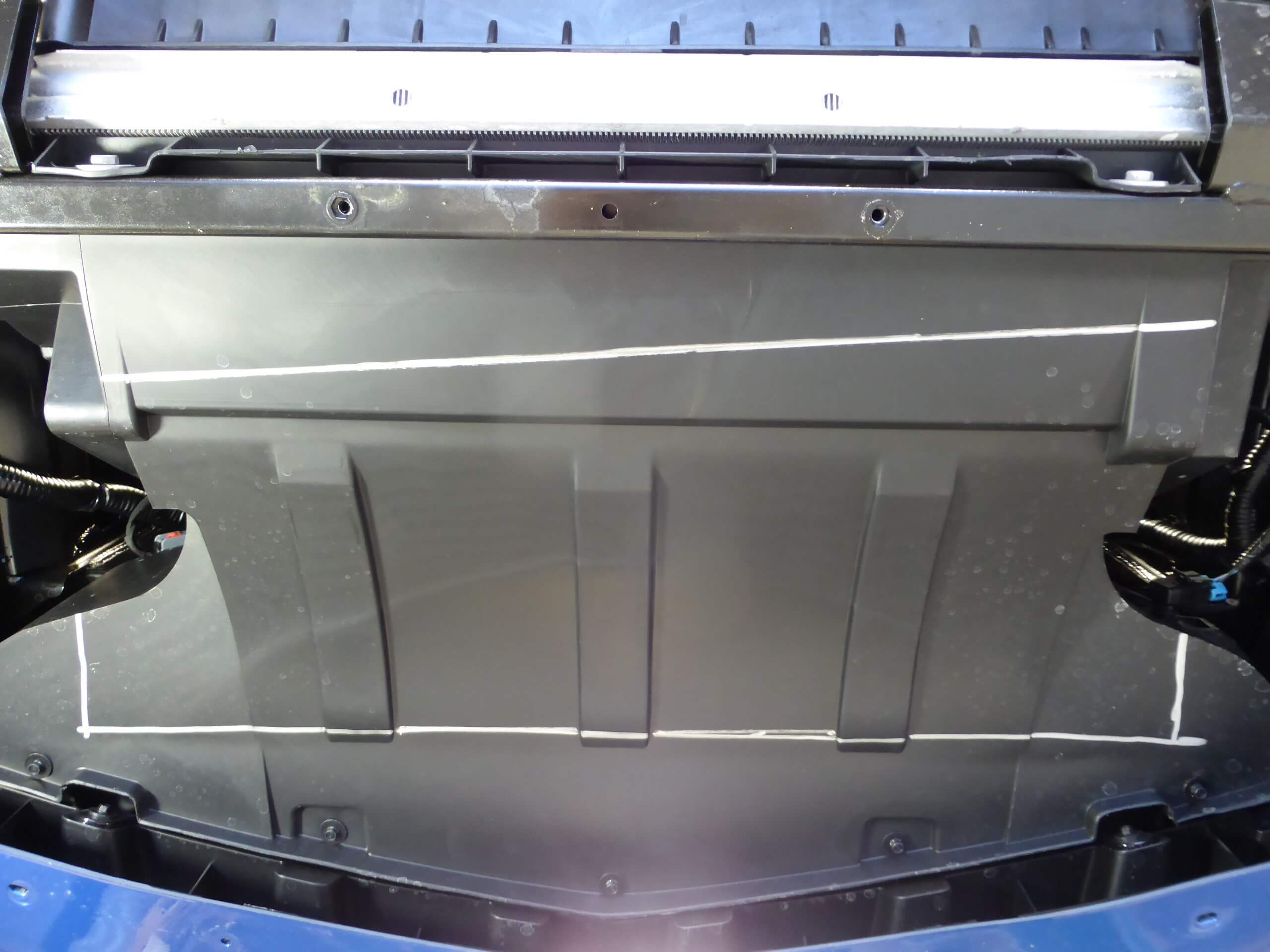
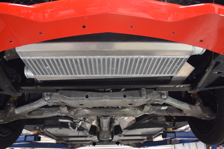
  • The A&A RAM AIR INTERCOOLER, and its integrated scoop will mount horizontally in front of the skid bar cross brace. Only the RAM AIR SCOOP will protrude into the radiator cavity once installed. The large plastic radiator shroud will need to be trimmed accordingly. This will require a little patience as you will need to trim the shroud a little at a time until you can position the intercooler in the correct location.


  • Proper front to back location is when the driver side mounting bracket will sit on top of the aluminum crossbar with the end of the bracket flush with the back edge of the crossbar. (see pictures below).

  • Side to side location is determined when the small bracket mounted to the side of the intercooler will fit between the intercooler and the side support.

THE DOTTED LINE INDICATES WHERE THE WELD BETWEEN THE INTERCOOLER CORE AND TANK SHOULD BE LOCATED
THIS IS THE OUTLINE OF THE INTERCOOLER SCOOP AND REAR TANK

  • You will need to visually make sure the intercooler is level and that the core is parallel with the crossbar. In the illustration above you’ll see a dotted line across the shroud right where the 45-degree bend is. Follow this bend and continue the line all the way to the end of the shroud. This line is where the weld on the intercooler should line up. Hold the intercooler up against the shroud using a piece of wood that approximates the intercooler core size on top of a floor jack or post jack. Line up the weld with this line and then trace around the rear and sides of the intercooler with a silver marker. Trace the outline of the front tank. to trace the line. Your outline will look like the above picture. (NOTE: The outline in front will actually mirror the one in the rear. The latest intercooler has angled tanks on both sides as opposed to a straight one as depicted in the picture).


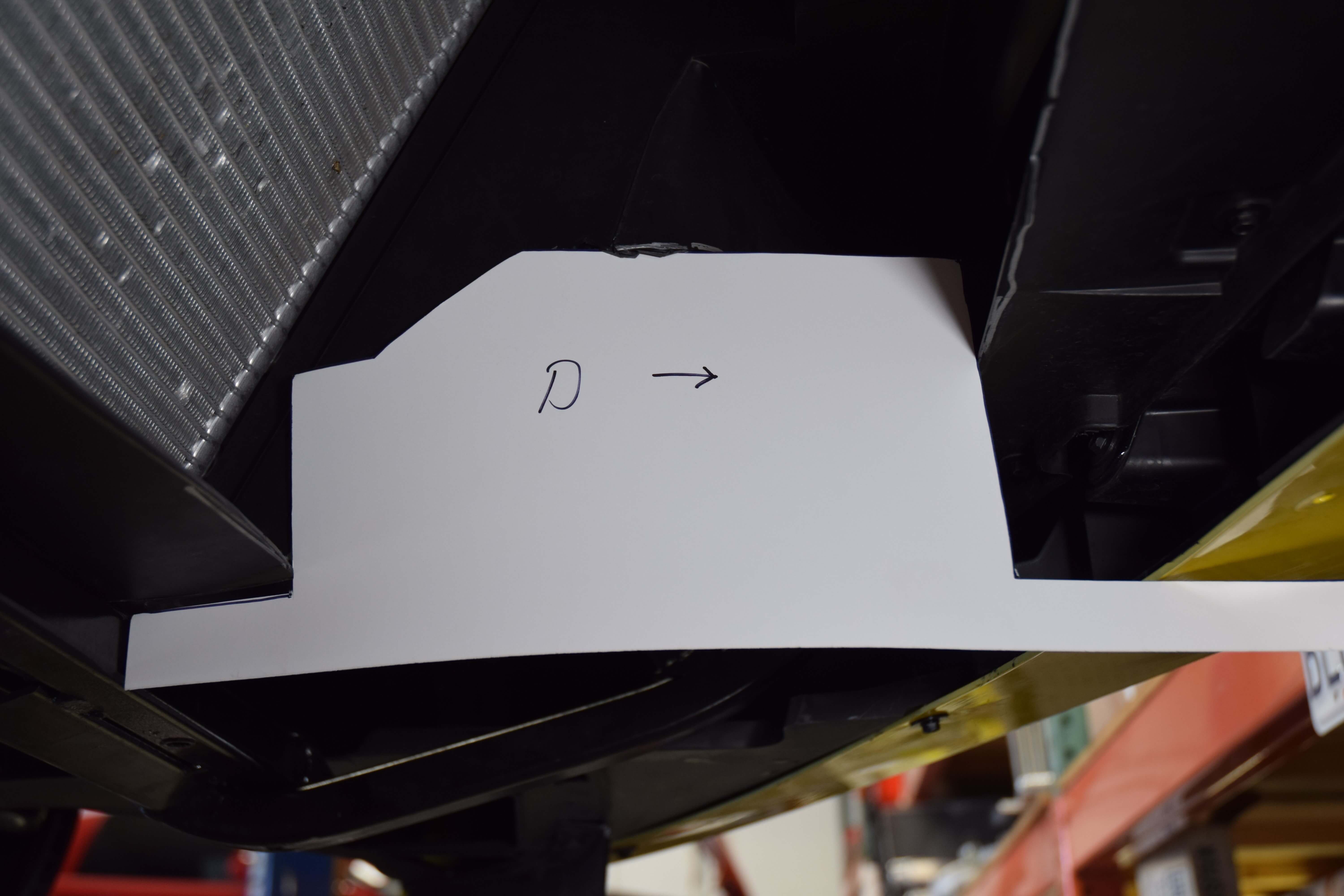
  •  Use the supplied templates to approximate how much to cut from the sides of the shroud. The rear of the template should touch the cross brace and the front should go under the fascia. The templates correspond with the shape of the intercooler and amount of plastic that needs to be trimmed from the side of the shroud. The templates are different from left to right and are marked so.

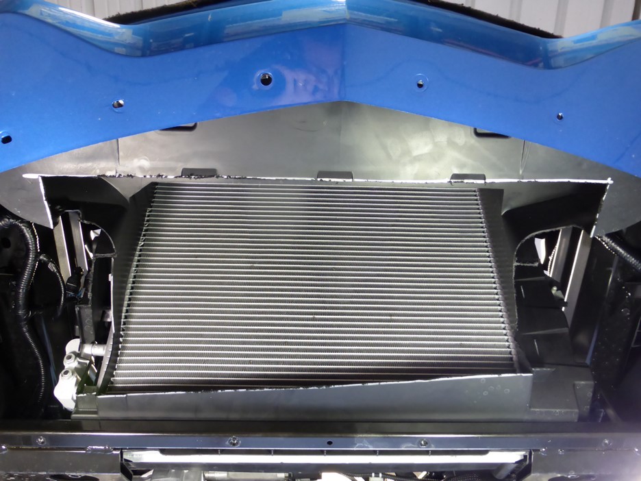
(INTERCOOLER OPENING AFTER BOTTOM AND SIDES ARE CUT)

  • Cut out your outline with a razor knife or saw. This piece is extremely odd in its shape and thickness. It will take some patience to get through this part. It’s best to cut inside the lines and then trim as needed.


  • NOTE: This piece is very inexpensive and we looked at including it in the kit. The problem is twofold. First is the fact that cutting it in the car is much easier than replacing it. Second is its size. The box required is almost as large as the whole kit, although very light. Shipping would be a very real issue.

(BOLTS GROUND FLUSH WITH NUT FOR CLEARANCE)

  • The large bracket on the left side (driver side) of the intercooler will rest directly on top of the cross brace with the end of the bracket being flush with the back of the brace. This is what determines the fore and aft placement of the intercooler. The right side (passenger side) of the intercooler will have a small mounting bracket that bolts to it and lines up with the diagonal strut on the skid bar assembly. This is what determines the left and right placement of the intercooler. 


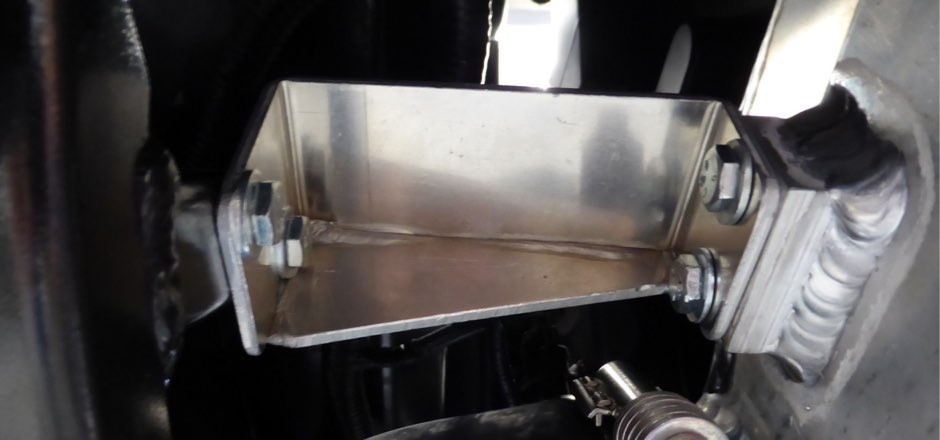
  • Once you’re sure the intercooler is in the correct position, mark the right side skid bar upright through the holes in the mounting bracket and drill two ¼” holes through the upright.


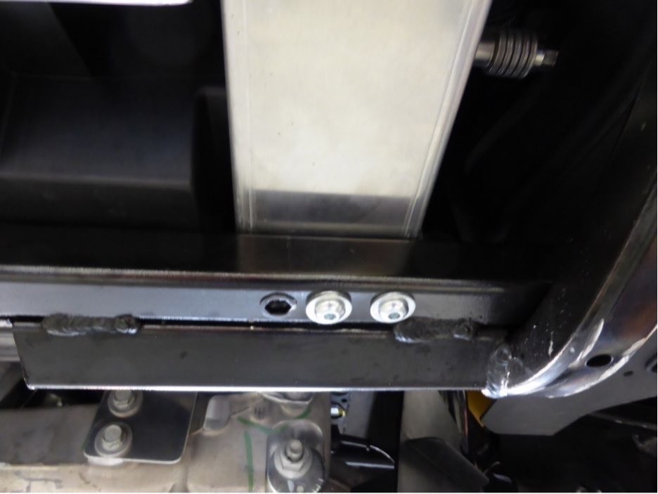
  • We purposely did not drill the mounting bracket on the left side. It sits directly on top of the skid bar cross brace making it easy to drill upwards through the cross brace and intercooler bracket all at once. The only real considerations are avoiding the threaded insert that is already in the cross brace and leaving enough room on either side for the ¼” nut. Install the supplied stainless button head bolts and nuts as shown.

(BUTTON HEAD BOLTS INSTALLED IN CROSSBAR)

RIGHT SIDE INTERCOOLER MOUNTING BRACKET INSTALLED

(A&A RAM AIR INTERCOOLER- PROPERLY INSTALLED)
FRONT VIEW – INTERCOOLER SCOOP IS ALL THAT IS SHOWING

INSTALL THE CHARGE TUBING FROM INTERCOOLER TO THROTTLE BODY

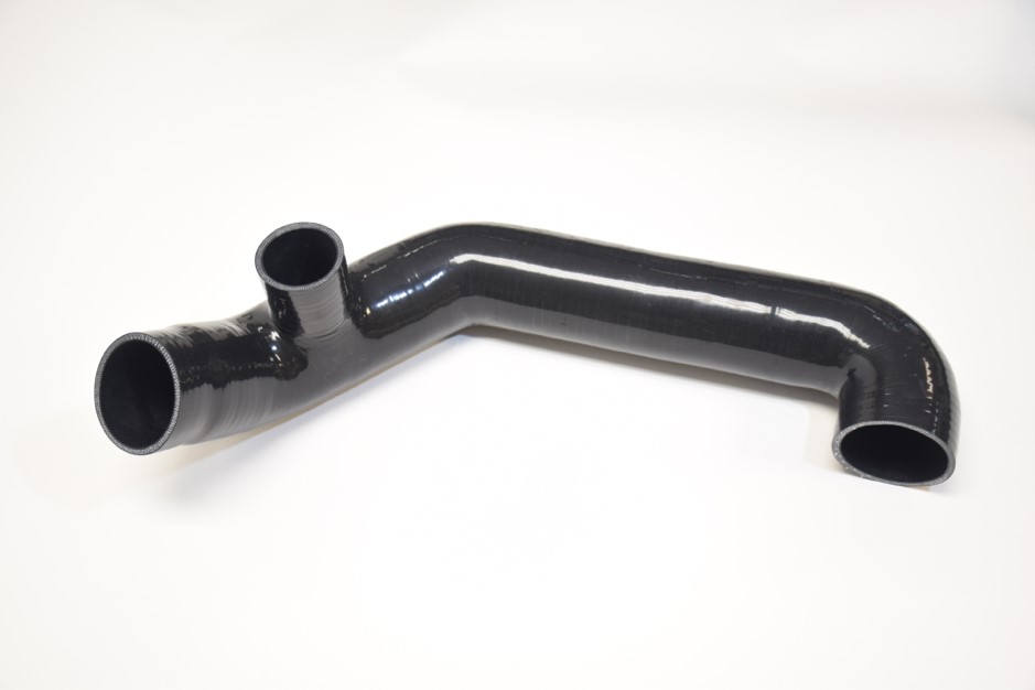
  • The right side (passenger side) silicone charge hose attaches to the discharge side of the intercooler, passes by the side of the radiator and ends up pointing upwards towards the throttle body at about a 45-degree angle. It is a tight squeeze to get the 90-degree bend onto the intercooler but it will go. Attach a constant tension clamp to the hose but leave it loose enough to move the hose if needed.


  • It is easiest to start on the engine side of the radiator support and push-pull the hose through to the front.


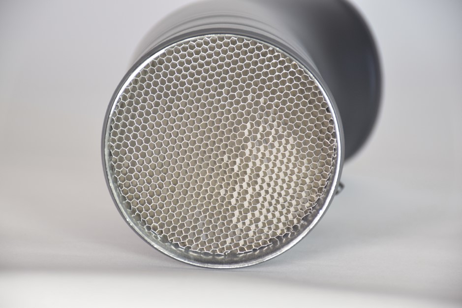
  • The MAF sensor tube is aluminum and has a honeycomb air straightener in the bottom. This piece makes the airflow over the MAF sensor much more linear which in turn helps tremendously with the tuning. The tube has an inverted bead rolled into the tube and is epoxied in place so there is no worry of the honeycomb piece coming loose. Just be careful not to damage the honeycomb material during installation.


  • Install the OE MAF sensor in the new MAF tube using a 9/64” Allen wrench with the new supplied screws. Insert the MAF tube into the silicone charge hose along with a stainless constant tension clamp and attach the other end of the tube to the throttle body with a silicone coupler and two constant tension clamps. Tighten clamps after making sure all connections are aligned properly.


  • Some cars seem to have a shorter MAF sensor wire harness than others. We have included a 6” extension harness with OE connectors to use if needed.

MAF TUBE INSTALLED AND ATTACHED TO INTERCOOLER HOSE- OUT OF CAR
(For display purposes only- install in vehicle separately)

(BE CAREFUL NOT TO DAMAGE THE ALUMINUM AIR STRAIGHTENER)

INSTALL CHARGE HOSE FROM SUPERCHARGER TO INTERCOOLER

  • Attach the 90-degree end to the intercooler inlet using a 3” constant tension clamp. Attach the other end of the assembly to the supercharger outlet using another clamp. Again, this area is very tight but will go on with some effort. It’s easiest to start from the engine side of the radiator support and push-pull the hose through to the front. 


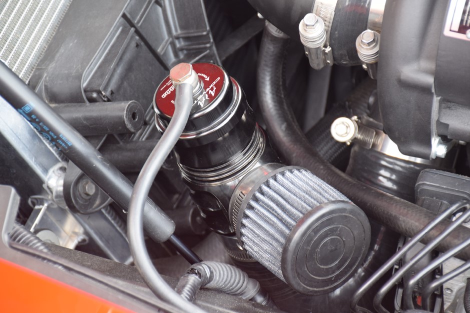
  • The blowoff valve (BOV) simply slips into the nipple on the charge hose and is clamped in place. If using a BOV with a filter, orient it towards the rear and slightly out.

(BOV FILTER ORIENTATION)

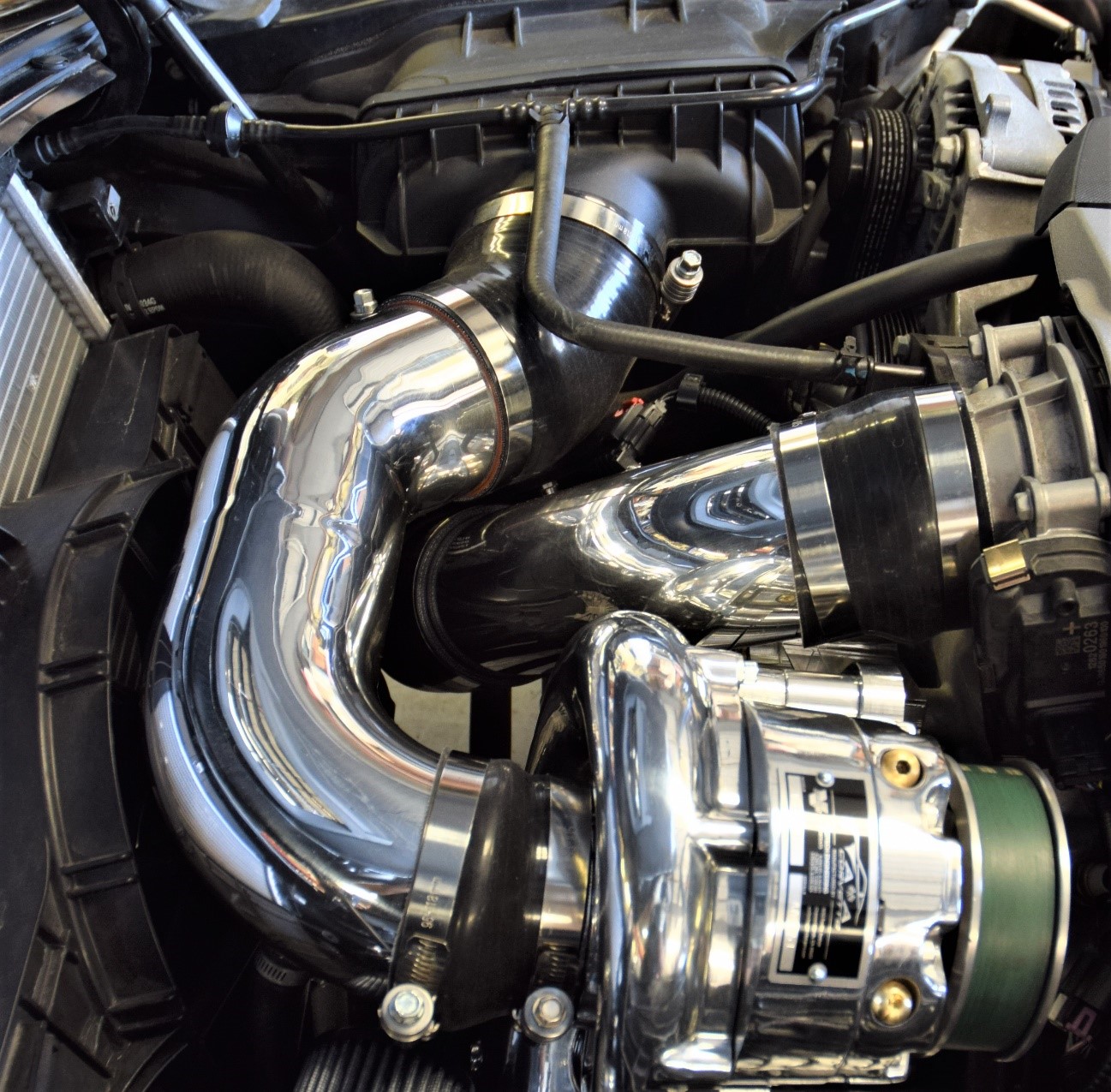
INSTALL THE 4” ALUMINUM AIR INTAKE TUBE

  • Install our custom high flow air filter in place of the stock unit and reinstall the modified airbox cover.


  • Attach the 45 degree 4 1/8” silicone coupler to the airbox cover first. Attach a 3 ½” to 4” silicone reducer over the supercharger inlet and clamp it in place.

  • (larger supercharger units use different sized couplers) Slip two clamps over the 45 degree coupler then slip the inlet tube into it. Slide a clamp over the supercharger coupler and slip the tube into it. Try to rotate the tube downwards to gain as much clearance as possible for the plastic radiator scoop. You can now tighten the clamps after aligning the tube. Be careful not to overtighten the clamp to the modified airbox as it can collapse.

  • On the passenger side, we use the stock crankcase vent hose. Simply snap the quick-connect ventilation hose onto the nipple. The nipple on the tube is welded shut to stop excess oil from being sucked into the intake. The large hose on the driver side provides adequate ventilation.

  • Disconnect the factory hose from the driver side valve cover and install our 5/8” hose and elbow in its place. There is a 5/8” nipple welded to the underside of the inlet tube. Simply clamp our 5/8” hose to the nipple. 

(4” AIR INLET AND MAF TUBES INSTALLED)

INSTALL CHECK VALVE AND VACUUM “T”

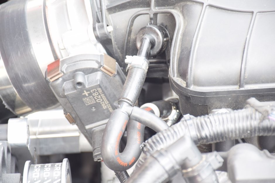
  • Replace the hose going from the engine valley cover to the intake manifold with our hose and check valve assembly. There is a Vacuum “T” in this assembly. Connect the supplied vacuum hose to this “T” and run it straight down to the BOV.

(NEW VENT HOSE WITH CHECK VALVE AND “T” FOR BOV)

(INTERCOOLER WITH PLAT PANEL INSTALLED)

CHECK YOUR WORK AND START IT UP

  • Go over your installation and make sure all your clamps are tight and that the silicone couplers are pushed onto the aluminum tubes far enough so that the clamps are behind the bead rolls in the tube.

  •  After starting the vehicle and making sure everything is operating correctly, you may install the engine covers as well as the radiator to hood heat extractor scoop. Install pieces of adhesive Velcro in the appropriate places on the underside of the scoop to prevent marring the finish on the inlet tube. 

  • Install the lower flat panel using the stock fasteners. Double check to make sure no fasteners or clips are rubbing on the intercooler core.

  •  Double check your clearance between the ABS box and the supercharger bracket.

  • The car will run but needs to be properly calibrated before any aggressive driving. It will go into limp mode with too much throttle application or could cause engine damage.

SUPERIOR CUSTOMER SERVICE BEFORE AND AFTER THE SALE

We want you to have the best experience possible when dealing with us both before and after the sale. You can always talk to a sales manager, the owner and head designer, or one of our techs who is infinitely knowledgeable on how the products operate and are installed. You won’t get a minimum wage customer service rep that knows nothing outside his or her script. You’ll get great advice based on many years of experience every time.


We’re happy to help you with your DIY install questions or product inquiries even after hours. The phones forward to either a Manager or Owner to help with both. Remembering that we are on Pacific time, you can generally get help until 9PM on weekdays and weekends alike. It’s something we started when the company was very young and have found it to be an invaluable resource to our customers.


TERMS & CONDITIONS


WARRANTY INFORMATION


PRIVACY POLICY

SHARE THIS PAGE!